Magnetizing & Electronics
Hall Sensor PCB Soldering Machine
Automatic soldering of phase leads and Hall sensor boards on BLDC stators.
Sensor-based BLDC motorsFan and pump motors
 Representative image
How it works
Built around your stator drawing
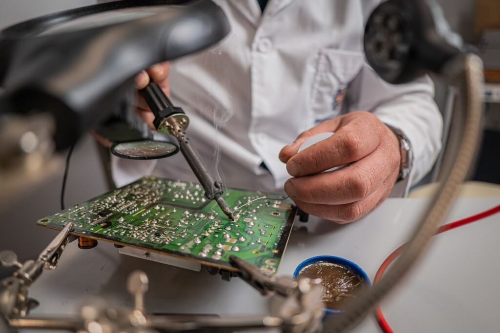
Many BLDC motors carry a Hall sensor board on the stator. This cell places the board, feeds solder wire and solders the phase leads with a temperature-controlled iron, then checks each joint on camera.
Key features
- 3- or 4-axis soldering robot
- Temperature-controlled iron with tip cleaning
- Solder wire feed per joint
- Camera joint inspection
- Fume extraction
 Part processed
Machine cycle
Process sequence
The order of operations in one cycle on this machine.
Technical data
Specifications
| Working area | 300 × 300 mm |
|---|---|
| Iron temperature | 200–450 °C |
| Control | PLC with 7–10 inch touch HMI, recipe storage |
| Power supply | 415 V AC, 3-phase, 50 Hz |
| Compressed air | 5–6 bar, dry and filtered |
Typical configuration. Every machine is customised to your motor design, and final values are confirmed in our quotation.
Options
Add-ons
- Selective wave soldering
- Conformal coating station
Machine video
Next step
Get a proposal for this machine
Send your stator or rotor drawing and target output. We reply with a machine configuration, cycle time estimate and price, and can run trial parts on request.
- Free design review of your motor drawing
- Trial winding or testing of your samples
- Installation, training and service across India